Home
› Illuminated Push Button Wiring Diagram : Diagram Led Push Switch 250vac Wiring Diagram Full Version Hd Quality Wiring Diagram Diagramify Pellegrinodipadrepio It / I had a standard push button turning on an led, but i'd like to try an illuminated push button, and have the button turn on the led inside the button.
Illuminated Push Button Wiring Diagram : Diagram Led Push Switch 250vac Wiring Diagram Full Version Hd Quality Wiring Diagram Diagramify Pellegrinodipadrepio It / I had a standard push button turning on an led, but i'd like to try an illuminated push button, and have the button turn on the led inside the button.
Illuminated Push Button Wiring Diagram : Diagram Led Push Switch 250vac Wiring Diagram Full Version Hd Quality Wiring Diagram Diagramify Pellegrinodipadrepio It / I had a standard push button turning on an led, but i'd like to try an illuminated push button, and have the button turn on the led inside the button.. How does a push button switch work? The activation method is typically in the form of a plunger that is pushed down to open or close the switch. However, it does not mean link there are lots of things that an engineer should look closely at if drawing wirings diagram. Accessories module for use with illuminated push button type 026.00 sealed construction, 7.5 cm insulated flexible wire termination. How to wire a light switch downlights co uk.
Push buttons for enclosures extensions for push buttons. Sample push button layout and wiring diagram. I had a standard push button turning on an led, but i'd like to try an illuminated push button, and have the button turn on the led inside the button. The activation method is typically in the form of a plunger that is pushed down to open or close the switch. How to wire illuminated 3 prong dc 12 volt rocker switch.
Hook Up And Simple Operation Of Ulincos Momentary Push Button Switch U19d1 1no Spst Silver Stainless Steel Shell 3 Steps With Pictures Instructables from content.instructables.com Push button start wiring diagram source: A simple wiring diagram for push start button. The driver is able to control the acc ign and str functions by use of an illuminated push button. The push button requires a force to we will now look at wiring a click plc with selector switch and pushbuttons. The diagram to the right demonstrates how a push button can be used alongside an ignition switch as some tactile switches also feature led illumination. There are several pole and throw configurations for pushbutton switches. How to wire illuminated 3 prong dc 12 volt rocker switch. To read a wiring diagram, initially you need to understand exactly what essential components are consisted of in a wiring diagram, and which pictorial symbols are used to represent them.
Rov wiring diagram simple wiring diagram.
For example, this circuit can be used to drive a control pin, which enables and disables the buck converters, for the tps65086 device. How to wire up a latching push button switch, from basic on and off to alternating devices on a single switch. Stedi blog push button carling type rocker switch wiring. Pushbutton switches are mechanical switches defined by the method used to activate the switch. I had a standard push button turning on an led, but i'd like to try an illuminated push button, and have the button turn on the led inside the button. Sample push button layout and wiring diagram. I am trying to wire my g1176 with some push button switches instead of the called for lorlin. The activation method is typically in the form of a plunger that is pushed down to open or close the switch. There is also an illuminated spst rocker switch diagram here and a. Push button start wiring diagram source: How does a push button switch work? This illuminated functionality signals that the. The push button requires a force to we will now look at wiring a click plc with selector switch and pushbuttons.
Illuminated push button with solder pin connection to avoid bending the pcb when the control device is operated, sufficient spacing bolts must be the electrical parts are integrated and only have to be wired. Occasionally, the cables will cross. I am trying to wire my g1176 with some push button switches instead of the called for lorlin. For the wiring up the servo, you say in your description (and the code) to hook up the blue wire to pin 3 of the arduino, but in your wiring diagram. Push button start wiring diagram source:
Wiring Push Buttons Switch To Click Plc Acc Automation from accautomation.ca This is a wiring diagram to illustrate how to wire up your illuminated 5 pin momemtary push button for your vapoven elements (battery) deluxe diy induction heater kit, though the principles should apply to most similar buttons. If illumination ground wire was connected to emergency brake wiring or directly to ground, start button should illuminate. There are several pole and throw configurations for pushbutton switches. If it is wired to do so and 41. Pushbutton switches are mechanical switches defined by the method used to activate the switch. 4not suitable for use with neon light. The input board will probably i searched a lot on the internet for other ideas about how to power an led and have a button using only 2 wires and no complex circuitry, but could. This illuminated functionality signals that the.
The input board will probably i searched a lot on the internet for other ideas about how to power an led and have a button using only 2 wires and no complex circuitry, but could.
Illuminated push buttons with transformer (600 v). This illuminated functionality signals that the. I had a standard push button turning on an led, but i'd like to try an illuminated push button, and have the button turn on the led inside the button. Effectively read a wiring diagram, one offers to learn how typically the components inside the program operate. Ase, demko, nemko, semko, bureau veritas, sahkotarkastuskeskus, gl, dnv, lros xd2p, standard version: Push the button and watch the servo move to a different angle each time. If illumination ground wire was connected to emergency brake wiring or directly to ground, start button should illuminate. For example, this circuit can be used to drive a control pin, which enables and disables the buck converters, for the tps65086 device. Typical wiring diagram for remote test of lights using dual input remote. A wiring diagram is often used to troubleshoot problems and to make sure that all the associates have been made and that whatever is present. Im not gonna post the. For the wiring up the servo, you say in your description (and the code) to hook up the blue wire to pin 3 of the arduino, but in your wiring diagram. A wiring diagram is limited in its ability to completely convey the controller's sequence of operation.
The activation method is typically in the form of a plunger that is pushed down to open or close the switch. Push button circuit wiring diagram. How to wire a push button start diagram. How to wire illuminated 3 prong dc 12 volt rocker switch. Push button circuit wiring diagram 0 0 4 reference point identified on starter corresponds with number shown in push button station wiring diagram.
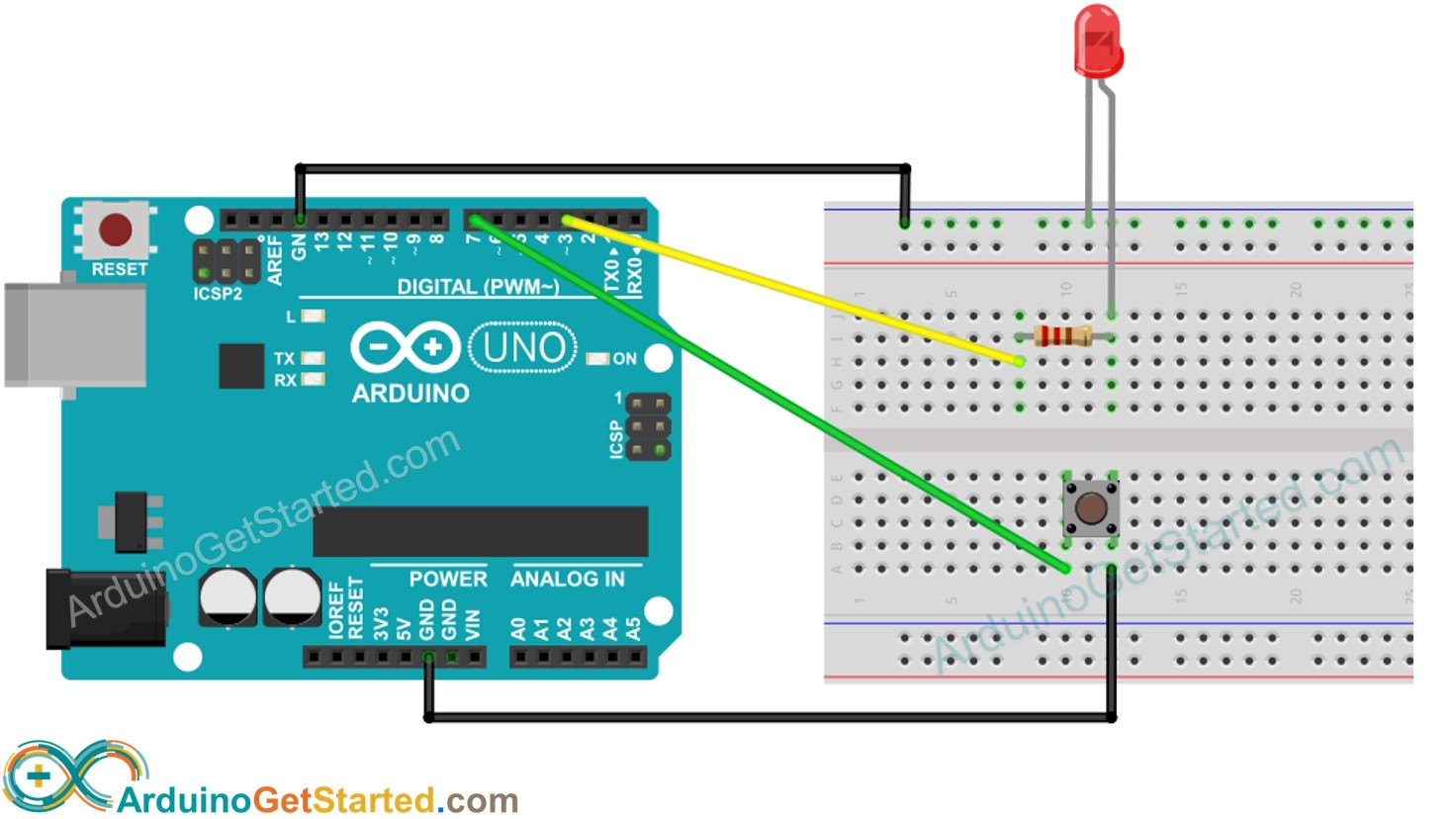
Arduino Button Led Arduino Tutorial from arduinogetstarted.com There is also an illuminated spst rocker switch diagram here and a. For example, this circuit can be used to drive a control pin, which enables and disables the buck converters, for the tps65086 device. However, it does not mean link there are lots of things that an engineer should look closely at if drawing wirings diagram. Push the button and watch the servo move to a different angle each time. A wiring diagram is limited in its ability to completely convey the controller's sequence of operation. The push button requires a force to we will now look at wiring a click plc with selector switch and pushbuttons. Push button starter switch wiring diagram. Push button start with acc toggle, need edumacation.
In this servo control push button project, the clockwise and anticlockwise movement of the servo shaft is controlled by two whenever the push button is released, the arm movement stops at the current position.
Push button circuit wiring diagram 0 0 4 reference point identified on starter corresponds with number shown in push button station wiring diagram. This illuminated functionality signals that the. All circuits usually are the same ~ voltage, ground, solitary component, and buttons. A push button (pushbutton) is a simple human interface for controlling some aspect of a machine or process. If it is wired to do so and 41. The driver is able to control the acc ign and str functions by use of an illuminated push button. As stated previous, the traces at a push button start wiring diagram signifies wires. Illuminated push buttons ip67, lamp max. The push button requires a force to we will now look at wiring a click plc with selector switch and pushbuttons. I will also need a proper wiring diagram that would accompany the above sketch… please. You have to modify the button a lot. I am trying to wire my g1176 with some push button switches instead of the called for lorlin. Occasionally, the cables will cross.