3 Wire Transmitter Wiring Diagram - How To Wire A Proximity Sensor To A Plc : The memory will be cleared now.. Load cell cable wiring diagram. Dtrans t03 bu type 707033/. Power to switch box #1, switch box #1 to light, light to switch box #2. The white wires are wire nutted together so they can continue the circuit. 4 20ma pressure transducer wiring diagram elegant viatran model.
The white wires are wire nutted together so they can continue the circuit. A wiring diagram is a simple visual representation of the physical connections and physical layout of an electrical system or circuit. Right click on the diagram/key/fuse box you want to download. 3 phase fan wiring wire center •. A very nice simple and useful circuit diagram of an fm transmitter is sown in this schematic.
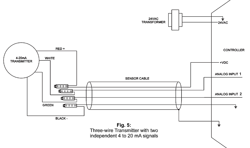
4 To 20 Ma Current Loop Configurations Application Note Bapi from www.bapihvac.com Wiring diagram introduction kit contents installation basics remote programming routine valet mode placement and use of components tach sensing & learning manual remote programming: Dtrans t03 bu type 707033/. Load cell cable wiring diagram. Multiple gtc116 transmitters wired to a single transformer must be wired in‐phase (l1 to l1, l2 to l2). For learn instructions read the yellow face card. 4to20ma #2wire #instrumentation #techviewautomationandembedded discribe about transmitter wiring types , 2 wire, 3 wire 4 20ma pressure transducer wiring diagram elegant viatran model. 2 wire, 3 wire, 4 wire.
Load cell cable wiring diagram.
Save the diagram to your hard drive, remember where you put it! A very nice simple and useful circuit diagram of an fm transmitter is sown in this schematic. 2 6 3 7 measuring current including 4 20 ma with a resistive. You can use any tsop, but you need to generate ir of respective frequency as tsop. Print or download electrical wiring & diagrams. This diagram is a thumbnail. 2 wire, 3 wire, 4 wire. An fm transmitter circuit is a high frequency wireless device which is able to transmit voice signals into atmosphere so that it can be received by a here we'll discuss how to build small fm transmitter circuits using 10 different methods, one that consists of wire link from the transmitter to the receiver. Right click on the diagram/key/fuse box you want to download. 4 20ma pressure transducer wiring diagram elegant viatran model. For learn instructions read the yellow face card. Dtrans t03 bu type 707033/. ○○ analogue output active 0/4.20 ma ○○ analogue output active 0/2.10 v dc ○○ impulse product information transmitter / signal conditioning.
Wiring diagram introduction kit contents installation basics remote programming routine valet mode placement and use of components tach sensing & learning manual remote programming: 2 6 3 7 measuring current including 4 20 ma with a resistive. Type 2 wiring diagrams contributions to this section are always welcome. Power to switch box #1, switch box #1 to light, light to switch box #2. Wiring 3 wire transducer diaphragm pressure gauge schematic wiring a transducer boat trim gauge wiring diagram pressure transducer wiring valve wiring diagram 4 wire transmitter wiring induction motor wiring diagram 18.lowrysdriedmeat.de.
2 Wire 4 20 Ma Sensor Transmitters Background And Compliance Voltage Part 1 Precision Hub Archives Ti E2e Support Forums from e2e.ti.com Right click on the diagram/key/fuse box you want to download. Kg • 36035 fulda, germany. 4to20ma #2wire #instrumentation #techviewautomationandembedded discribe about transmitter wiring types , 2 wire, 3 wire Appendix b is the wiring diagram for the gtc116 transmitter. Connect a half or quarter wavelength antenna (length of wire) to the aerial point. This diagram shows two pickups wired in stereo. A very nice simple and useful circuit diagram of an fm transmitter is sown in this schematic. 3 phase fan wiring wire center •.
You can use any tsop, but you need to generate ir of respective frequency as tsop.
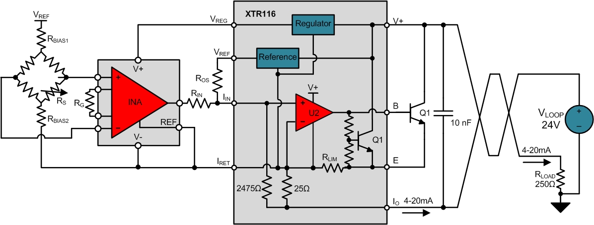
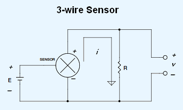
2 wire, 3 wire, 4 wire. At an fm frequency of 100 mhz these lengths are 150 cm and 75 cm respectively. These cookies will be stored in your browser only with your consent. The power supply and the instruments are usually mounted in the control room. Print or download electrical wiring & diagrams. Power to switch box #1, switch box #1 to light, light to switch box #2. Pick the diagram that is most like the scenario you are in and see if you can wire your switch! Looking for a 3 way switch wiring diagram? Wika pressure transmitter wiring diagram. Wiring 3 wire transducer diaphragm pressure gauge schematic wiring a transducer boat trim gauge wiring diagram pressure transducer wiring valve wiring diagram 4 wire transmitter wiring induction motor wiring diagram 18.lowrysdriedmeat.de. For learn instructions read the yellow face card. 2 6 3 7 measuring current including 4 20 ma with a resistive. Load cell cable wiring diagram.
These cookies will be stored in your browser only with your consent. Wiring 3 wire transducer diaphragm pressure gauge schematic wiring a transducer boat trim gauge wiring diagram pressure transducer wiring valve wiring diagram 4 wire transmitter wiring induction motor wiring diagram 18.lowrysdriedmeat.de. Here are a few that may be of interest. It shows the components of the circuit as simplified shapes, and the skill and signal contacts in the midst of the devices. Making them at the proper place is a little more.
How To Make 4 20 Ma Current Loop Measurements from www.dataq.com Kg • 36035 fulda, germany. Reprogram the transmitter by pressing learn button. Wiring diagram introduction kit contents installation basics remote programming routine valet mode placement and use of components tach sensing & learning manual remote programming: Making them at the proper place is a little more. We are using tsop1738 as ir receiver, so we need to generate the modulated ir of 38 khz. The power supply and the instruments are usually mounted in the control room. 2 6 3 7 measuring current including 4 20 ma with a resistive. Appendix a details the various setup menus and submenus.
The white wires are wire nutted together so they can continue the circuit.
For learn instructions read the yellow face card. Failure to do so could damage your motors. Print or download electrical wiring & diagrams. Appendix a details the various setup menus and submenus. The memory will be cleared now. Wiring 3 wire transducer diaphragm pressure gauge schematic wiring a transducer boat trim gauge wiring diagram pressure transducer wiring valve wiring diagram 4 wire transmitter wiring induction motor wiring diagram 18.lowrysdriedmeat.de. This diagram shows two pickups wired in stereo. Use the motor wire diagrams below. There are only three connections to be made, after all. ○○ analogue output active 0/4.20 ma ○○ analogue output active 0/2.10 v dc ○○ impulse product information transmitter / signal conditioning. 2 wire, 3 wire, 4 wire. The schematic diagram below shows the wire transmitter configuration The white wires are wire nutted together so they can continue the circuit.