Control Circuit Diagram / Servo Motor Control Using 555 Timer IC / That is why instructions for projects usually include a.. This circuit control diagram template offers plenty of circuit diagram symbols. Design circuits online in your browser or using the desktop application. Of the two gates of ic cd40106b , n1 is wired as an inverting schmitt trigger astable. Here the circuit arranged to toggle the output for each positive triggering at the clock input of the decade. Tone control circuit is the circuit, using which we can control the output of audio device.
Hopefully the post content article control circuit diagram. This is very simple circuit with few electronics components. One of the clocks is wired as an astable multivibrator to produce the. This circuit control diagram template offers plenty of circuit diagram symbols. Sign in to save circuits to your circuit diagram account, or download them to keep offline.
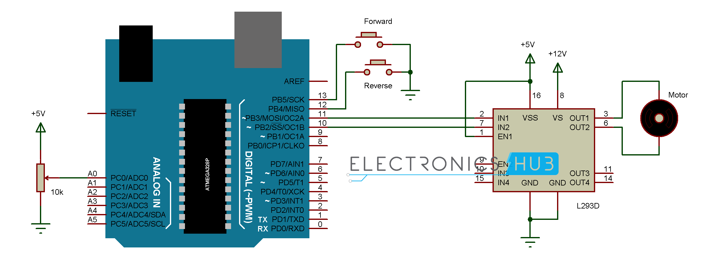
DC Motor Control With Arduino from www.electronicshub.org There are 164 circuit schematics available in this category. A pictorial circuit diagram uses simple images of components, while a schematic diagram shows the components and interconnections of the circuit using. These questions & answers will help you master the topic! Circuit diagram of automatic street light control is given below. __ designed by tony van roon va3avr. Star delta starter power circuit wiring diagram. This is very simple circuit with few electronics components. Rgb led light wall washer circuit diagram.
Here the circuit arranged to toggle the output for each positive triggering at the clock input of the decade.
The variation in speed is achieved by varying the duty cycle of the pulse supplied to drive the motor. These two different types of circuit diagrams are called pictorial (using basic images) or schematic style (using. Control symbols are used in line diagrams, also referred to as ladder diagrams. A diagram is a two dimensional geometric symbolic representation of information. The actual layout of the components is usually quite a circuit diagram is useful when testing a circuit and for understanding how it works. One of the clocks is wired as an astable multivibrator to produce the. Some circuits would be illegal to operate in most countries and others are dangerous to construct and should not be attempted by the inexperienced. Ladder diagrams are specialized schematics commonly used to document industrial control logic systems. Ladder diagrams differ from regular schematic diagrams of the sort common to electronics technicians primarily in the strict orientation of the wiring: Circuit diagram is a free application for making electronic circuit diagrams and exporting them as images. Control circuits:schematic diagrams , wiring diagrams the first circuit to be discussed is a basic control circuit used related searches for motor control circuit diagram control panel wiring diagram3 phase motor wiring diagramelectric motor wiring basicsdc motor. This is very simple circuit with few electronics components. Pwm or pulse width modulation is a very common method used for controlling the power.
Digital temperature controller circuit diagram, it is used to controls the temperature of any device according requirements for any. Monolithic circuit shown in fig time transmitter circuit xr2242, timing time from a few milliseconds to a few days. These questions & answers will help you master the topic! Take the ac motor control circuits (ac electric circuits) worksheet. Some circuits would be illegal to operate in most countries and others are dangerous to construct and should not be attempted by the inexperienced.
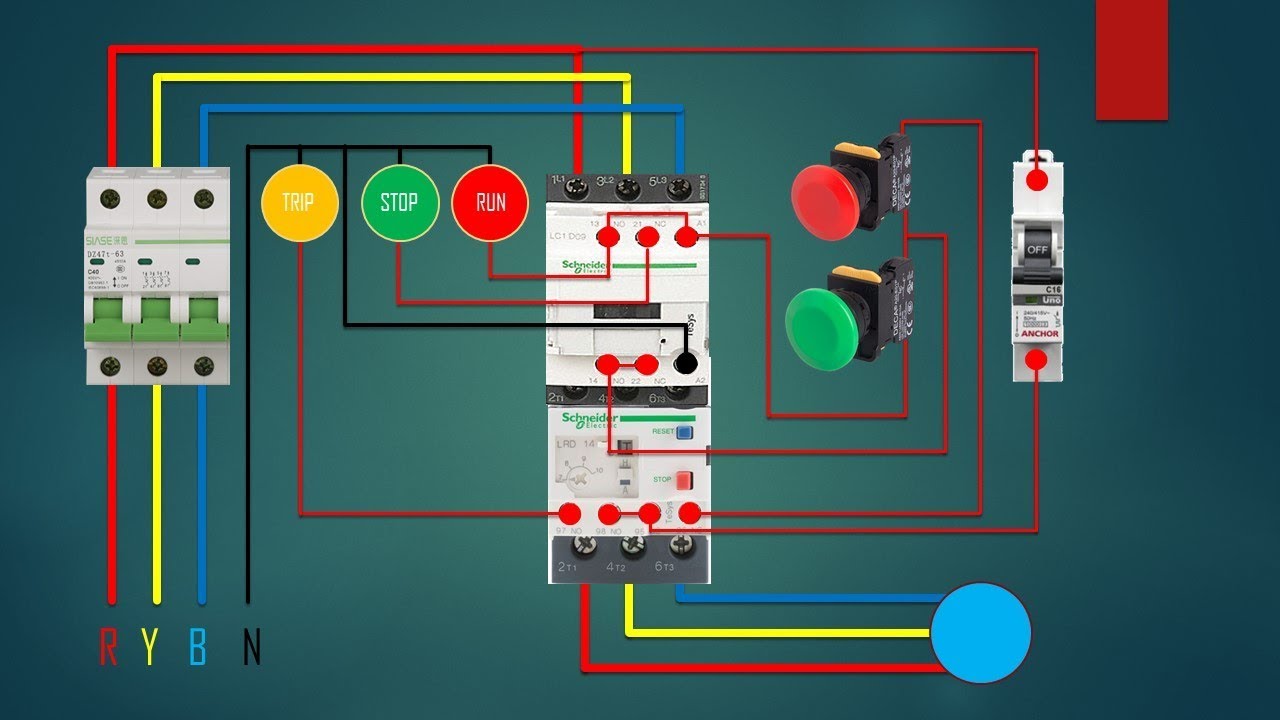
three phase dol starter Control overload Indicator Power Wiring diagram - YouTube from i.ytimg.com They are called ladder diagrams. The receiver circuit is similar to a latching switch which on and off the output alternatively for each triggering. These questions & answers will help you master the topic! Chart sample flowchart representing the decision process to add a new article to wikipedia. Circuit diagram of automatic street light control using light dependent resistors. Hopefully the post content article control circuit diagram. One of the clocks is wired as an astable multivibrator to produce the. Here is a simple pwm motor speed controller circuit that can be used for varying the speed of low power dc motors.
They are called ladder diagrams.
Circuit diagram of automatic street light control is given below. The variation in speed is achieved by varying the duty cycle of the pulse supplied to drive the motor. Hopefully the post content article control circuit diagram. Here the circuit arranged to toggle the output for each positive triggering at the clock input of the decade. One of the clocks is wired as an astable multivibrator to produce the. Digital temperature controller circuit diagram, it is used to controls the temperature of any device according requirements for any. Ladder diagrams are specialized schematics commonly used to document industrial control logic systems. A circuit diagram is a visual display of an electrical circuit using either basic images of parts or industry standard symbols. Three phase dol starter control overload indicator power wiring diagram. Perhaps the most challenging aspect of interpreting ladder diagrams, for people more familiar with electronic schematic. The circuit comprises a time base oscillator, a binary counter 8 and a control trigger. Click here for all circuit diagrams. Here is the circuit diagram of stereo digital volume control.
You can use it as a start template to draw circuit control or electrical schematic diagrams. The last circuit was added on thursday, november 28. Perhaps the most challenging aspect of interpreting ladder diagrams, for people more familiar with electronic schematic. Take the ac motor control circuits (ac electric circuits) worksheet. Three phase dol starter control overload indicator power wiring diagram.
Automatic Street Light Controller Using Relays and LDR from www.electronicshub.org Take the ac motor control circuits (ac electric circuits) worksheet. Symbol usage depends on the audience viewing the diagram. There are 164 circuit schematics available in this category. The receiver circuit is similar to a latching switch which on and off the output alternatively for each triggering. This circuit control diagram template offers plenty of circuit diagram symbols. This is a simple project of contrast control circuit diagram for lcds. Star delta starter power circuit wiring diagram. Circuitdiagram.net provides huge collection of electronic circuit design :
Circuit diagram:the value of r1 can be calculated as follows:
Chart sample flowchart representing the decision process to add a new article to wikipedia. Here is a simple pwm motor speed controller circuit that can be used for varying the speed of low power dc motors. Friends in this video i will show you ir remote controlled switch.simple remote control circuit diagram.easily make ir sensor. The receiver circuit is similar to a latching switch which on and off the output alternatively for each triggering. A circuit diagram is a visual display of an electrical circuit using either basic images of parts or industry standard symbols. These two different types of circuit diagrams are called pictorial (using basic images) or schematic style (using. The same would be true if the scr gate had a continuous bias. The actual layout of the components is usually quite a circuit diagram is useful when testing a circuit and for understanding how it works. Click here for all circuit diagrams. Circuit diagram of automatic street light control using light dependent resistors. Home » circuits » ir remote control circuit diagram. Circuit diagrams show the connections as clearly as possible with all wires drawn neatly as straight lines. Where t is the temperature in kelvin and i is the current.