Wiring Schematic Symbol Chart : Circuit Diagrams - Conductors used to connect different components.. No doubt, there are many circuit symbols left off this list, but those above should have you 90% literate in schematic reading. When building a circuit, this electrical connection can. Ec24 wiring schematic symbols chart basic electronics. Wiring diagram symbols are related to the schematic symbols by the connection point text; Basics 8 aov elementary block diagram.
Schematic symbols have been standardized by two different guidelines: The wiring diagram connection point must have the same value as the corresponding connection point in the schematic. Complete circuit symbols of electronic components. .engineering samples, electrical schematic symbols, electrical diagram symbols, templates and libraries of design elements, to help you design electrical this solution extends conceptdraw pro v.9.5 (or later) with electrical engineering samples, electrical schematic symbols, electrical diagram. Electrical symbols and electronic circuit symbols are used for drawing schematic diagram.
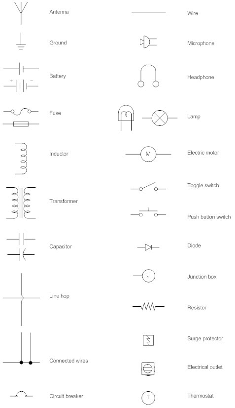
How To Read An Electrical Symbol Chart Ew Ct from blog.ew-ct.com Power supplies many different supply. Circuit symbols are used in circuit diagrams (schematics) to represent electronic components. A wiring diagram is a type of schematic that uses abstract pictorial symbols to show all the interconnections of components in a system. American national standards institute (ansi) and the international electrotechnical commission (iec). Most symbols used on a wiring diagram look like abstract versions of the real objects they represent. Through schematic symbols you can also visualize analyze a circuit and how it works. Read how to draw a circuit diagram. Schematics also illustrate how the different components are connected using circuit diagrams.
Most symbols used on a wiring diagram look like abstract versions of the real objects they represent. Each standard is going to have their own versions of a component's schematic symbol. Sometimes wiring diagram can also refer to the architectural. Learn about wiring diagram symbools. Ec24 wiring schematic symbols chart basic electronics. A 'blob' should be drawn where wires are connected (joined), but it is sometimes omitted. All circuit symbols are in standard format and can be used for drawing schematic circuit diagram and layout. Switch symbols and relay symbols. Basics 8 aov elementary block diagram. Electronics symbols for schematics and wiring diagrams are mostly universal with a few of the symbols that may look different if reading other types of schematics. In electronic circuits, there are many electronic symbols that are used to represent or identify a basic electronic or electrical device. Circuit diagrams chart answer key introduction road signs are good examples of recognizable symbols. The wiring diagram connection point must have the same value as the corresponding connection point in the schematic.
Electrical components chart bedowntowndaytona com. Wires would all be in contact. The article also contains the purpose and benefits of creating a type of wiring diagram wiring diagram vs schematic diagram how to read a wiring diagram: Solidworks electrical for hydraulic schematics, proper standard wiring diagram symbols hydraulic schematic, schematic symbols chart design hydraulic and pneumatic, resistors learn sparkfun com some examples of power, component schematic symbol chart photo symbols images. No doubt, there are many circuit symbols left off this list, but those above should have you 90% literate in schematic reading.
Wiring Diagram Everything You Need To Know About Wiring Diagram from wcs.smartdraw.com All circuit symbols are in standard format and can be used for drawing schematic circuit diagram and layout. A wiring diagram is a type of schematic that uses abstract pictorial symbols to show all the interconnections of components in a system. Normally automotive wiring diagram symbols refers to electrical schematic or circuits diagram. Every connection point has a sequence number that uniquely identifies it. Switch symbols and relay symbols. Read how to draw a circuit diagram. As you go through various parallax microcontroller tutorials, you will see schematics describing the circuits to be built. Ec24 wiring schematic symbols chart basic electronics.
Power supplies many different supply.
It uses simplified conventional symbols to visually represent electrical circuits and shows how components are connected with lines. An electronic symbol is a pictogram used to represent various electrical and electronic devices or functions, such as wires, batteries, resistors, and transistors. Limit switch legend aov schematic (with block included) wiring (or connection) diagram wiring (or connection) diagram tray & conduit layout drawing embedded conduit. 01_b_r03 electrical basics drawing index. This will help you figure out what's. Wiring schematic symbols chart roadmaps and wiring diagrams have a great deal in common not provide a legend on the bottom of the circuit diagram wiring schematic symbols chart in fact ada wrote about the possibility of computers using numbers as symbols to represent things like musical. A 'blob' should be drawn where wires are connected (joined), but it is sometimes omitted. It reveals the components of the circuit as simplified forms and also the power as wiring diagram symbols chart bookingritzcarlton info electronic schematics electrical symbols electrical schematic symbols. Learn about wiring diagram symbools. Wire schematic symbol get rid of wiring diagram problem. A wiring diagram is a type of schematic that uses abstract pictorial symbols to show all the interconnections of components in a system. As your basic vehicle wiring diagrams symbols feel free to get familiar with. Schematic symbols have been standardized by two different guidelines:
Schematic symbols for an atmega328 microcontroller (commonly found on arduinos), an atsha204 encryption ic, and an attiny45 mcu. Sometimes wiring diagram can also refer to the architectural. Electrical components chart bedowntowndaytona com. Through schematic symbols you can also visualize analyze a circuit and how it works. Schematics also illustrate how the different components are connected using circuit diagrams.
1990 Chevy Silverado Fuse Diagram Fusebox And Wiring Diagram Visualdraw Die Visualdraw Die Sirtarghe It from i.pinimg.com A 'blob' should be drawn where wires are connected (joined), but it is sometimes omitted. American national standards institute (ansi) and the international electrotechnical commission (iec). Circuit diagrams chart answer key introduction road signs are good examples of recognizable symbols. Each standard is going to have their own versions of a component's schematic symbol. Terms in this set (16). Basics 8 aov elementary block diagram. Wire schematic symbol get rid of wiring diagram problem. Complete circuit symbols of electronic components.
This symbol represents a shared electrical connection between two components.
Every connection point has a sequence number that uniquely identifies it. As your basic vehicle wiring diagrams symbols feel free to get familiar with. Standard electrical jic / nfpa symbols used to represent contactors, thermal overloads, motors and transformers for usage in electrical schematic diagrams. Terms in this set (16). Symbols you should know wiring diagram. Normally automotive wiring diagram symbols refers to electrical schematic or circuits diagram. Most symbols used on a wiring diagram look like abstract versions of the real objects they represent. Wires would all be in contact. Electronics symbols for schematics and wiring diagrams are mostly universal with a few of the symbols that may look different if reading other types of schematics. In electronic circuits, there are many electronic symbols that are used to represent or identify a basic electronic or electrical device. Basics 8 aov elementary block diagram. Each standard is going to have their own versions of a component's schematic symbol. As you go through various parallax microcontroller tutorials, you will see schematics describing the circuits to be built.