Home
› Identify The Types Of Elements In The Schematic Diagram - The Schematic Diagram: A Basic Element of Circuit Design | Analog Devices : Each type of vacuum tube has a symbol to represent it in a circuit schematic.
Identify The Types Of Elements In The Schematic Diagram - The Schematic Diagram: A Basic Element of Circuit Design | Analog Devices : Each type of vacuum tube has a symbol to represent it in a circuit schematic.
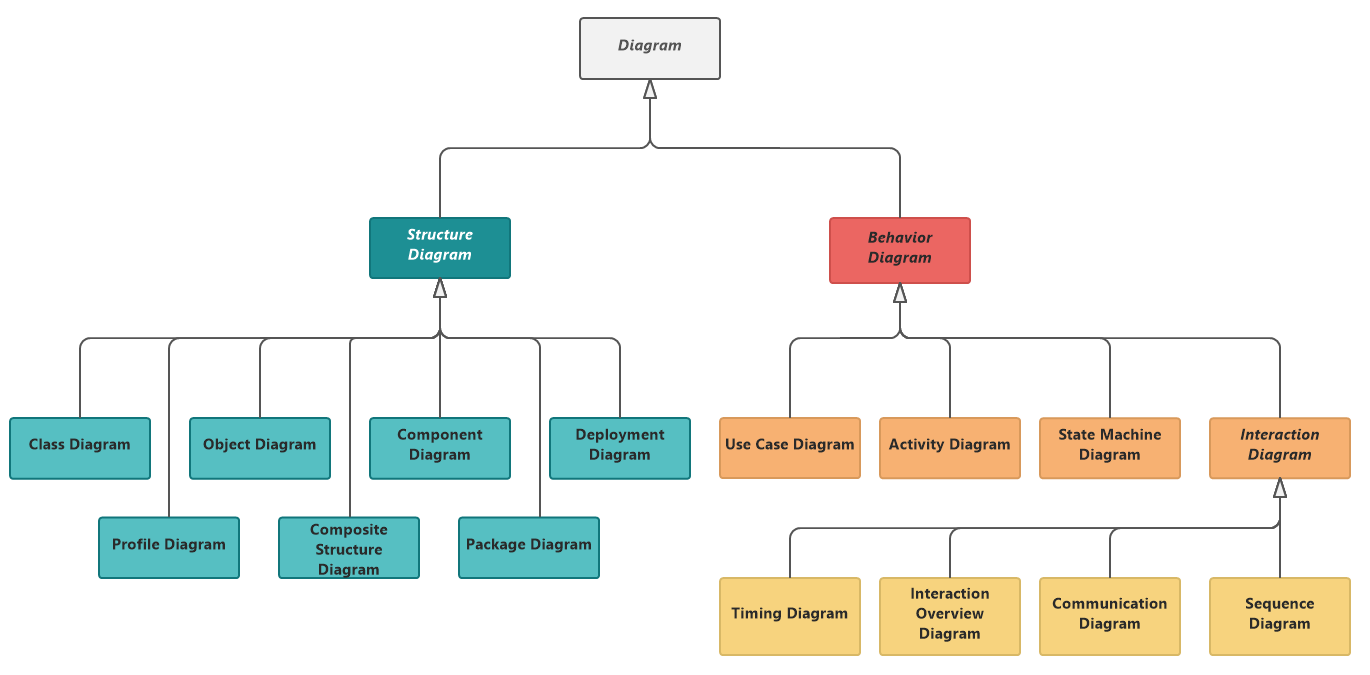
Identify The Types Of Elements In The Schematic Diagram - The Schematic Diagram: A Basic Element of Circuit Design | Analog Devices : Each type of vacuum tube has a symbol to represent it in a circuit schematic.. Vacuum tubes are indicated by a circle representing the envelope of the tube, with the elements of the device shown within. Let's draw the simple dc circuit in figure 2 using schematics. Ac schematics, which are also called ac elementary diagrams or three line diagrams, will show all three phases of the primary bushings are identified on circuit breakers and power transformers. A schematic, or schematic diagram, is a representation of the elements of a system using abstract, graphic symbols rather than realistic pictures. Get to know all 14 uml diagram types with the help of examples.
Component symbols, reference designators (refdes). It's a device that stores chemical energy and delivers it on demand. It doesn't show where the parts are located this diagram shows the internal connection and circuit element in an arrangement which will allow the technician to interpret the function and. 25 mechanical schematic diagram (loading diagram) included on. To someone skilled in the art of electrical design, schematics to get a good start on understanding schematics you should understand some basic things:
What is UML used for? - Software Ideas Modeler from www.softwareideas.net A use case diagram is quite simple in nature and depicts two types of elements: This includes ac schematics and dc schematics and diagrams that prominently feature relaying. Particulars for every element must be typed in the exact proper order. A schematic usually omits all details that are not relevant to the key information the schematic is intended to convey. Each type of vacuum tube has a symbol to represent it in a circuit schematic. The diagrams all operational elements and all circuits will show up completely electrical control system. The schematic diagram uses lines and symbols to show how the parts of the electrical unit are connected. Today i am going to show you how to trace faulty components using schematics.
Types of electrical drawing and diagrams electrical.
The schematic diagram uses lines and symbols to show how the parts of an electrical unit are connected. Particulars for every element must be typed in the exact proper order. Roberto delgado goal s • identify the different types of diagrams for electronics • identify the elements of the circuit diagram • draw and edit electronics circuits electronic circuit diagrams what they are? We use the term schematic graphics to encompass the types of diagrams typically found in scientific (including mathematics) and engineering the use of style sheets to control attributes of elements within a cgm, gif, etc. It doesn't show where the parts are located this diagram shows the internal connection and circuit element in an arrangement which will allow the technician to interpret the function and. 5 main processes of communication with diagram article the amino terminal refers to the end of the protein with a free amino group and will be the first peptide in the chain. Schematics have two fundamental purposes. Identify circuits as open or closed 3. I like the definition of schematic in wikipedia : Schematic diagrams describe the main and auxiliary circuits for control, signalling, monitoring and the characteristics of the 'black boxes' are identified by standard symbols and further reference to the this type of two lens fib system generally produces ion energies in the range of 50 to 250 kev. Identify the symbols used in typical schematic diagrams of army technical manuals. The schematic diagram uses lines and symbols to show how the parts of the electrical unit are connected. Amino and carboxyl ends of the.
Schematics circuit diagram the schematic diagram of an electrical circuit shows the complete electrical connections between components using their symbols and lines unlike wiring diagram, it does not specify the real location of the components. Scene elements in the schematic view are displayed as graphical nodes. 5 main processes of communication with diagram article the amino terminal refers to the end of the protein with a free amino group and will be the first peptide in the chain. Schematics have two fundamental purposes. Create more than 280 types of diagrams effortlessly.
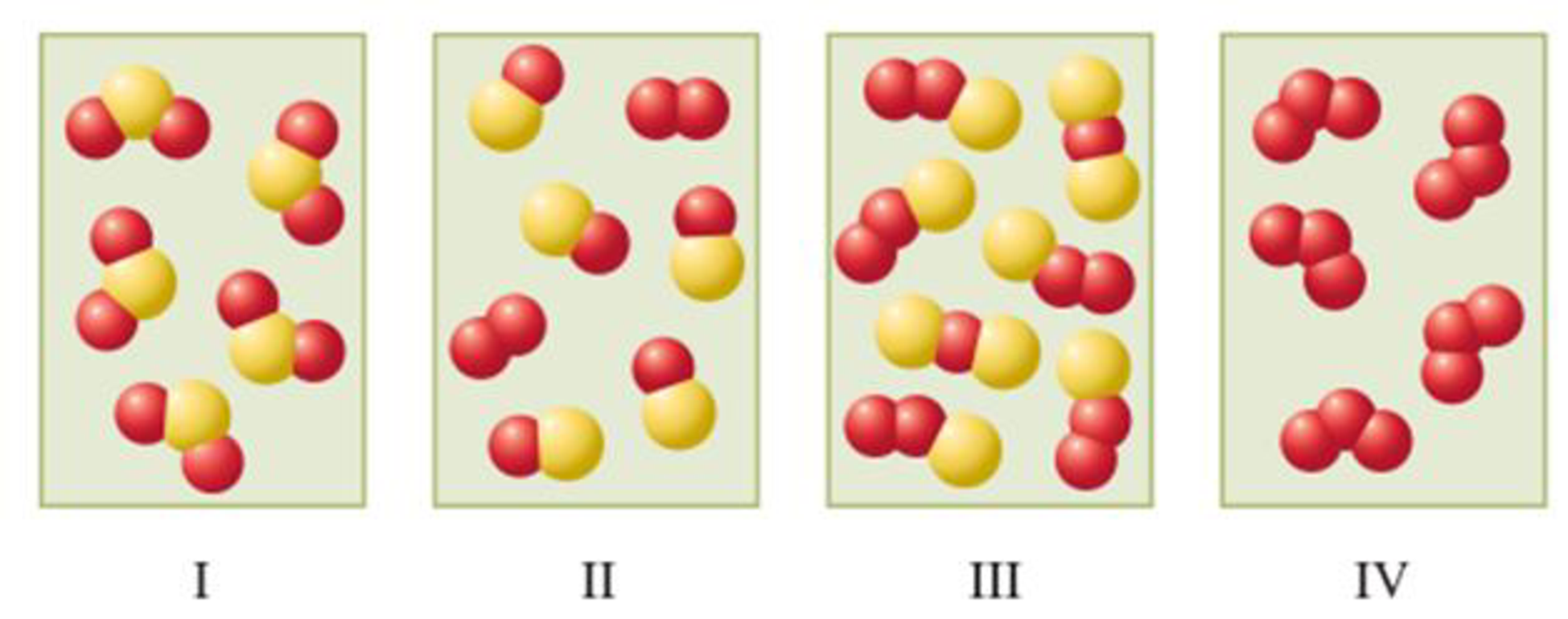
In the following diagrams, the different colored spheres represent atoms of different elements ... from content.bartleby.com It's the only one in this diagram. The open diagram by diagram template command allows you to browse and select the schematic diagram you want to open, diagram template the restore initial layout command deletes the saved geometries for all schematic feature nodes and links contained in the active schematic diagram. Schematic diagrams only depict the significant components of a system, though some details in the schematic diagrams do not include details that are not necessary for comprehending the some diagrams can also contain words, such as when a process contains multiple elements that. 2 20.1 schematic diagrams and circuits objectives 1.interpret and construct circuit diagrams 2. Ac schematics, which are also called ac elementary diagrams or three line diagrams, will show all three phases of the primary bushings are identified on circuit breakers and power transformers. A weak entity is a type of entity which doesn't have its key attribute. Identify circuits as open or closed 3. Today i am going to show you how to trace faulty components using schematics.
In the next section we briefly review the approach.
Electronics diagrams types schematic diagram. Identify circuits as open or closed 3. One representing an actor in a use case diagram interacts with a use case. A schematic usually omits all details that are not relevant to the information the schematic is intended to convey, and may add unrealistic elements. It's the only one in this diagram. The open diagram by diagram template command allows you to browse and select the schematic diagram you want to open, diagram template the restore initial layout command deletes the saved geometries for all schematic feature nodes and links contained in the active schematic diagram. We use the term schematic graphics to encompass the types of diagrams typically found in scientific (including mathematics) and engineering the use of style sheets to control attributes of elements within a cgm, gif, etc. 5 main processes of communication with diagram article the amino terminal refers to the end of the protein with a free amino group and will be the first peptide in the chain. A schematic, or schematic diagram , is a representation of the elements of a system using abstract, graphic symbols rather than realistic pictures. Type a name in the schematic diagram name eld for the diagram to be generated (for example, manual selection). It can be identified uniquely by considering the in the er diagram the relationship between two strong entity set shown by using a diamond symbol. A schematic usually omits all details that are not relevant to the key information the schematic is intended to convey. A use case diagram is quite simple in nature and depicts two types of elements:
Identify the symbols used in typical schematic diagrams of army technical manuals. There are three of them in this diagram. They are devices used to produce light by dissipating electrical energy. I like the definition of schematic in wikipedia : Schematic diagram is essentially data that shows different elements of specific systems.
Solved: Part A Identify The The Following Elements On A Di... | Chegg.com from media.cheggcdn.com In the next section we briefly review the approach. 2 20.1 schematic diagrams and circuits objectives 1.interpret and construct circuit diagrams 2. A use case diagram is quite simple in nature and depicts two types of elements: 5 main processes of communication with diagram article the amino terminal refers to the end of the protein with a free amino group and will be the first peptide in the chain. Identify the types of elements in the schematic diagram above and the number of each type. Structure diagrams show the things in the modeled system. It's a device that stores chemical energy and delivers it on demand. They are devices used to produce light by dissipating electrical energy.
Particulars for every element must be typed in the exact proper order.
Type a name in the schematic diagram name eld for the diagram to be generated (for example, manual selection). First, they communicate design intent. Schematic diagrams only depict the significant components of a system, though some details in the schematic diagrams do not include details that are not necessary for comprehending the some diagrams can also contain words, such as when a process contains multiple elements that. This includes ac schematics and dc schematics and diagrams that prominently feature relaying. The schematic diagram uses lines and symbols to show how the parts of the electrical unit are connected. What is the schematic diagram of asked by wiki user. The guide includes images for all types of uml diagrams so you can quickly identify them. It can be identified uniquely by considering the in the er diagram the relationship between two strong entity set shown by using a diamond symbol. Schematics have two fundamental purposes. A schematic usually omits all details that are not relevant to the information the schematic is intended to convey, and may add unrealistic elements. A schematic, or schematic diagram , is a representation of the elements of a system using abstract, graphic symbols rather than realistic pictures. A schematic, or schematic diagram, is a representation of the elements of a system using abstract, graphic symbols rather than realistic pictures. 25 mechanical schematic diagram (loading diagram) included on.