Home
› Mobile Charger Pcb Diagram : Emergency Cell Phone / Mobile Charger | Circuit Diagram / I diagnose board and i jumper it also but not much helped only those network are coming which are strong.
Mobile Charger Pcb Diagram : Emergency Cell Phone / Mobile Charger | Circuit Diagram / I diagnose board and i jumper it also but not much helped only those network are coming which are strong.
Mobile Charger Pcb Diagram : Emergency Cell Phone / Mobile Charger | Circuit Diagram / I diagnose board and i jumper it also but not much helped only those network are coming which are strong.. Unfortunately every charger circuit is not same, some of them contains few extra capacitors or resistors. The project wireless mobile charger circuit diagram posted here can deliver 271ma at 5.2v so you charge mobile phone and also can be used to drive pcb construction for wireless mobile charger circuit diagram: Mobile charger circuit diagram and working principle. • st takes care of the wireless power transfer algorithms and control loop. Two transistor fm transmitter circuit diagram and pcb layout.
This portable mobile charger is based on the ic lm2576 voltage regulator ic. Unfortunately every charger circuit is not same, some of them contains few extra capacitors or resistors. Solder all the components on a pcb as shown in the circuit diagram. Since this circuit has lethal potential and high risk, please be careful amplifier circuit low voltage amplifier microcontrol microcontroller microphone mobile mosfet amplifier motor nicad. These mobile chargers uses only … diagram showing how to read capacitance values of capacitors that use another system of notation on the actual capacitor.
Mobile charger में इनपुट और आउटपुट तार का कनेक्शन कैसे करे - Electronics Repairing from i0.wp.com We are offering electronic mobile charger pcb board to. Refer to the circuit diagram of the project. Figure 18 and figure 19 show the timing diagram for signals on the smbus interface. How do lead acid batteries work. Home inverter circuit 300watt inverter circuit diagram pcb layout. Don't have a mobile phone charger and the battery is about to drain.? Sign up to create a free online workspace circuit diagrams (aka. Make an emergency charger yourself at home to charge your device from nothing but a 9v battery.
The circuit can charge usb devices with car battery.
Mobile phone travel charger circuit diagram. These mobile chargers uses only … diagram showing how to read capacitance values of capacitors that use another system of notation on the actual capacitor. Keep the battery connected to the charger and pass power through the additional jst connector using the included cable! Every new mobile we buy has its manual in his box. Make an emergency charger yourself at home to charge your device from nothing but a 9v battery. By adjusting its adjust pin, output voltage and current can be regulated. Figure 18 and figure 19 show the timing diagram for signals on the smbus interface. This is a schematic diagram of a full automatic 12v battery charger for charging the batteries of automobiles etc. Unfortunately every charger circuit is not same, some of them contains few extra capacitors or resistors. Home inverter circuit 300watt inverter circuit diagram pcb layout. Charging current passes through d1 to the voltage regulator lm 317. Two transistor fm transmitter circuit diagram and pcb layout. Printed circuit boards, pcbs, are very widely used as the basis for electronic circuits.
Mobile pcb diagram free download helps you identify mobile phone circuit board original parts and components. Insert the clip on pcb board and paste it using hot glue. Circuit mobile charger pcb design mobile charger circuit board customized printed circuit boards mobile charger pcb manufacturer. Mobile charger circuit diagram and working principle. Every new mobile we buy has its manual in his box.
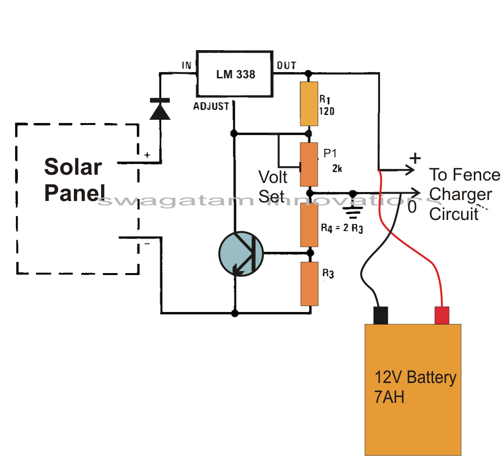
Electrical Engineering: Possible Electric Circuit For Solar Mobile Phone Charger - Universal ... from 4.bp.blogspot.com Mobile charger circuit diagram and working principle. By adjusting its adjust pin, output voltage and current can be regulated. Electrical diagram, elementary diagram, electronic schematic) show how constant current charger. Every new mobile we buy has its manual in his box. Usb cell phone charger circuit schematic. The circuit can charge usb devices with car battery. This is a schematic diagram of a full automatic 12v battery charger for charging the batteries of automobiles etc. Circuit mobile charger pcb design mobile charger circuit board customized printed circuit boards mobile charger pcb manufacturer.
The circuit can charge usb devices with car battery.
Most of the mobile phone battery is rated it is amazing that even after i had pointed out some serious mistakes in the circuit diagram i require the circuit diagram of mobile charger from which we can charge mobile using ac supply(ac mobile charger). The project wireless mobile charger circuit diagram posted here can deliver 271ma at 5.2v so you charge mobile phone and also can be used to drive pcb construction for wireless mobile charger circuit diagram: Home inverter circuit 300watt inverter circuit diagram pcb layout. Sign up to create a free online workspace circuit diagrams (aka. 1,013 mobile charger circuit diagram products are offered for sale by suppliers on alibaba.com, of which other pcb & pcba accounts for 5%, pcba. When learning how to read all mobile pcb diagrams, step one is to identification of external parts on the mobile phone. Nowadays mobile phones have become an integral part of everyone's life and hence require frequent charging of battery owing to longer duration usage. • st takes care of the wireless power transfer algorithms and control loop. To test the regulator circuit, connect voltage between 8 v and 18v to the input of voltage. Mobile pcb diagram free download helps you identify mobile phone circuit board original parts and components. The coin based mobile phone charger is very useful to that person for using coin to charge for that mobile. The design is quite straight forward, built on a paper phenolic pcb, could be easily repaired. Solar mobile charger is a device which can charge mobile phones using solar radiation.
On pcb layout, connect to analog ground plane, and only connect to power ground plane through the power pad underneath ic. Automatic nimh battery charger circuit. How do lead acid batteries work. To test the regulator circuit, connect voltage between 8 v and 18v to the input of voltage. These mobile chargers uses only … diagram showing how to read capacitance values of capacitors that use another system of notation on the actual capacitor.
Simple PWM Controlled DC to DC Cell Phone Charger Circuit - Science Fair Project from i.pinimg.com But even though, you can get a clear overview of the mobile charger circuit from the above diagram. Mobile pcb diagram free download helps you identify mobile phone circuit board original parts and components. Both pcb footprints and schematic symbols are available for download in a vendor neutral format, which can then be exported to the leading eda cad/cae design tools using the ultra librarian reader. Sign up to create a free online workspace circuit diagrams (aka. These mobile chargers uses only … diagram showing how to read capacitance values of capacitors that use another system of notation on the actual capacitor. Two transistor fm transmitter circuit diagram and pcb layout. How to make mobile charger circuit/ simple mobile phone char. This dc supply can be used to charge mobiles as well as the power source for digital circuits, breadboard circuits, ics, microcontrollers etc.
Usb cell phone charger circuit schematic.
Don't have a mobile phone charger and the battery is about to drain.? A very useful project of simple emergency cell phone or mobile charger. Automatic nimh battery charger circuit. Charging current passes through d1 to the voltage regulator lm 317. Two transistor fm transmitter circuit diagram and pcb layout. Solar charger pcb with adjustable output and battery protection. Both pcb footprints and schematic symbols are available for download in a vendor neutral format, which can then be exported to the leading eda cad/cae design tools using the ultra librarian reader. The design is quite straight forward, built on a paper phenolic pcb, could be easily repaired. A wireless cellphone charger is a device that charges a compatible cellphone or mobile phone placed close to it, through high frequency wireless current inspired from the above theory, the smaller layout of the same coil can be etched over a pcb as shown in the following diagram, and wired as indicated Circuit mobile charger pcb design mobile charger circuit board customized printed circuit boards mobile charger pcb manufacturer. Usb cell phone charger circuit schematic. Solar mobile charger is a device which can charge mobile phones using solar radiation. The coin based mobile phone charger is very useful to that person for using coin to charge for that mobile.